Testing Fiber Optic Cables
2021-08-17
All fibers in a cable plant should be tested at least for continuity, proper end to end connections and, most importantly, loss. How each of these tests are performed depends on the installation type, required standards and the actual layout of the components in the cable plant.
Actually, there are five industry standard ways of testing the loss of a fiber optic cable – three for insertion loss and two for OTDRs – depending on how you use reference test cables for your setup. Insertion loss testing with a test source and power meter with reference cables (right) can use 1, 2 or 3 reference cables to set the “zero dB loss” reference for testing and each way gives a different loss. Generally standards prefer the 1 reference cable loss method, but it requires that the test equipment uses the same fiber optic connector types as the cables under test. If the cable has different connectors than the test equipment (e.g. LCs on the cable and SCs on the tester), it may be necessary to use a 2 or 3 cable reference, which will give a lower loss since connector loss is included in the reference and will be subtracted from the total loss measurement. Any of the three methods are acceptable, as long as the method is documented. Be careful, however, as most network link losses assume a 1 cable reference, which can affect the acceptance of the cable.
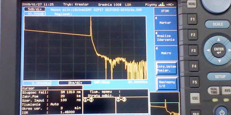
OTDRs always require a launch cable for the instrument to settle down after reflections from the high powered test pulse overloads the instrument. OTDRs have traditionally been used with long distance networks where only a launch cable is used, but this method does not measure the loss of the connector on the far end. Adding a cable at the far end allows measuring the loss of the entire cable, but negates the big advantage of the OTDR, that it makes measurements from only one end of the cable.

OSP cables are typically long distance singlemode cables that are installed in short sections, usually 5-12 km max depending on the cable size, since the bulk and weight of the cable determines how long is the longest cable that can be installed. Shorter lengths may be common in urban or campus networks, as cable is installed between junction points which are determined by the geography of the cable plant. Since shorter lengths of cable are spliced together, verification of the splices is important and is usually done with an OTDR test during the installation process. Once installation is complete, end-to-end insertion loss is done with a test source and optical power meter, sometimes called an OLTS (optical loss test set) and reference test cables. Certain ultra-long distance cables may require more complex testing for chromatic or polarization-mode dispersion.
The accuracy of testing these long singlemode fibers with multiple splices depends on many factors. Since the fibers are long, the attenuation of the fiber is an important part of the measured loss. Since the attenuation coefficient of the fiber is dependent on the wavelength of the light source, small differences in the wavelength of a test source (in either an OLTS or OTDR) can lead to significant differences in the measured loss. The only way to minimize this variation is to use test sources as close to the nominal wavelengths as possible (1310 and 1550 nm typically, althoght others may be specified.)

OTDRs depend on fiber backscatter for making measurements, so any difference in fiber backscatter at a splice will lead to higher loss in one direction and lower loss (or a gain) in the other direction. The only way to accurately measure splice loss is to measure in both directions and average, a tedious process in a long, large fiber count cable. One can get an idea of the magnitude of the uncertainty of the measurement by looking at the attenuation coefficient of the fiber on either side of the splice. It the two fibers are nearly equal, the directional variation will be small, but if they are large, big differences may be found.
How To Choose Fiber Optic Cables?
Fiber Optic Cable Installation Tutotrial
Related Article


1、Core Definition and Working Principle
2、 Key Characteristics
3、 Main Classifications
4、Core Differences from Multimode Fiber
5、Typical Application Scenarios
2、 Key Characteristics
3、 Main Classifications
4、Core Differences from Multimode Fiber
5、Typical Application Scenarios
What is single-mode fiber optic?